I want to do a rotating, aerodynamically improved (not quite wing-) mast. This is a kind of "proof of concept" model, although perhaps "evidence of concept" is more accurate. The shrouds go through holes in the boat-shaped board and their tension is held by the spring clamps. The mast is supported on the tip of a drywall screw. I wanted to see what effects leaving the spreaders free to pivot would have, as the mast rotates. So far, nothing goes over-center, or otherwise gets wonky. The model stick responds to tune as you'd expect, and the loaded (weather) side actually stays pretty static so that the mast doesn't displace much at all as it rotates. I'll talk to people smarter than me before I go ahead, but I like it so far.

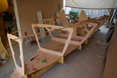
I decided to do things a little (more) differently. After seeing the shape of the panels once they're propped into place, I just couldn't see how pulling the curving panels tight against straight frames was going to be a good thing. The panels looked very fair as they were, so why mess with a good thing? So I took patterns from the side panels at each frame location and used those to cut a matching curve into each frame. I added a notch for a sheer clamp and mid-panel stringer as well. This pic shows all the frames dry fit, just propped up in place.

And here's some progress. I added a kevlar tape reinforcement under the fore-and-aft bits, and then bonded in frames 169 and 124. The keel box is being fitted now, and then it and frame 110 will go in together. I have some diagonal and fore and aft stuff going in front of the transom, and behind 110 as well, which also still needs to be bonded to the bottom.

I must say that I like having the access to the hull bottom that this build sequence provides- I can reach all the middle bits without (hardly) stepping into the boat.


.jpg)


my hull panels are all slightly curved as well.
ReplyDeleteIt makes a few things tough to join up in the end, like the sheer line, but nothing a little extra work couldn't solve. I believe over stressing the hull, from what it wants to do naturally, is not the way to go.
looks good
-Chris
I was going to leave the side panels an inch wide along the shear line to be trimmed to fit on the boat, but thought, "naw, these dimensions are producing some nice fair curves, they must be right..." Kicking myself, now. I'm going to have a continuous fair piece of wood for a sheer clamp anyway, which would have made an excellent guide for zipping off any excess ply. Oh well- I don't think the distances are much different between a straight line frame and these gently arched ones, so at worst my side panels will be an eighth low of the plan shear, but backed by solid wood so a bit o putty should work just fine.
ReplyDeletehello
ReplyDeletewhat benefits are there of putting the kevlar down? i can see why you would do it under the structural beams but why in the bow? just spare?
what do you gain by using changed structure below the deck? lighter? stronger?
I had the kevlar, so that's part of it. I really wanted to strengthen/stiffen the boat fore and aft, and diagonally. The kevlar acts as the tension side to a continuous I-beam that runs from each end of the traveller forward to almost the bow.
ReplyDeleteThe boats need excess weight put into them to make weight, so why not spend it well?
edit:
Had to leave earlier, didn't finish...
Clearly, the boats need more stringers/panel stiffeners in various places. I thought it would be best to add the stiffeners in a way that also tied the deck and hull of the boat together into more of a box beam.
I changed the shape of the cutouts in the frames to suit my own whims. For instance, I didn't see the usefulness of a 1" wide piece of 1/4" ply to support the house (frame 89). I intend to make the house from shaped corecell foam anyway (because I've always wanted to figure out how to use the stuff), so that ribbon of ply wasn't useful to me. There's a similar really skinny piece where the cockpit corner is on frame 124. Then, on frame 169 I thought the area with the holes could just be a ring frame. I'm adding a diagonal set of half-frames between the chainplates and the mast step to add some stiffness there as well. So I've cut away what I thought was fat, and put in what I thought was thin.
I added about an 1 1/2" of side-to-side curvature to the cockpit sole to stiffen it as well.